Executive Summary & Key Technical Takeaways
Quick Summary: A Membrane Bioreactor (MBR) is an advanced wastewater treatment technology that combines conventional biological degradation (activated sludge) with low-pressure microporous membrane filtration. By substituting traditional gravity clarifiers with ultrafiltration or microfiltration barriers (0.04 to 0.1 micron pore size), MBR systems operate at double to triple the biomass concentration (MLSS 8,000 to 12,000 mg/L). This engineering setup delivers crystal-clear effluent with Total Suspended Solids (TSS) under 2 mg/L, Turbidity below 0.2 NTU and Silt Density Index (SDI) under 3.0, making it the ideal pre-treatment stage for Reverse Osmosis (RO) and Zero Liquid Discharge (ZLD) systems.
Civil Footprint
Reduction
Tensile Breaking
Strength
Guaranteed TSS
Effluent
Uniform
Ultrafiltration Pore
1. Introduction: The Evolution of Wastewater Treatment
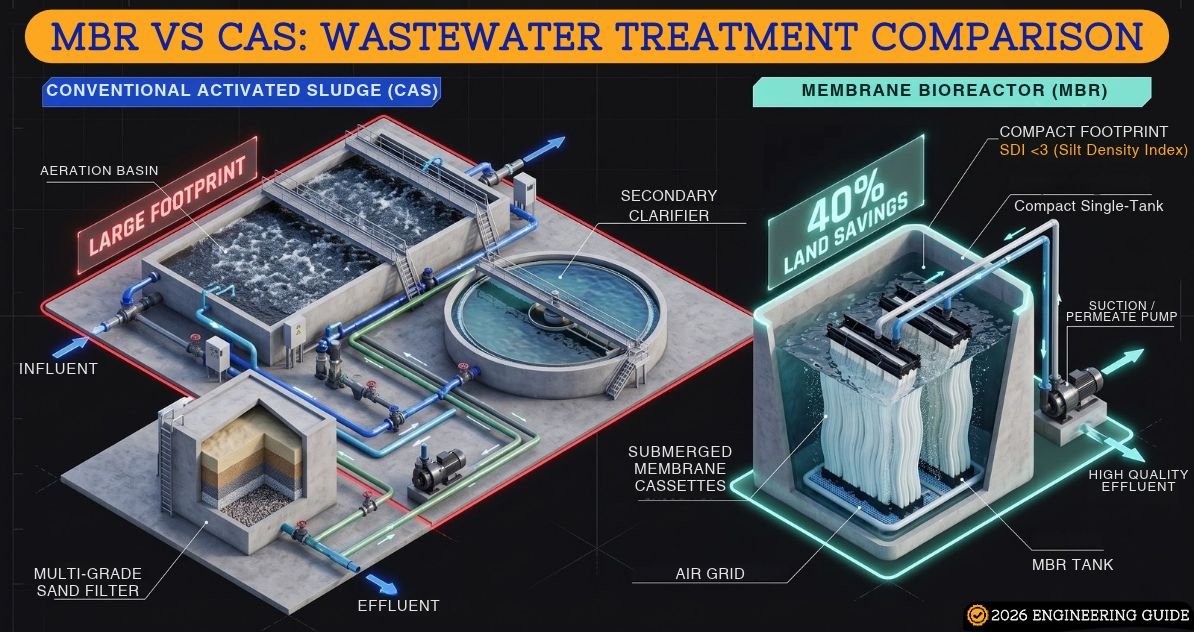
Strict environmental discharge regulations from the Central Pollution Control Board (CPCB) and State Pollution Control Boards (SPCB) across India have pushed conventional treatment plants to their operational limits. Traditional wastewater treatment systems rely on Conventional Activated Sludge (CAS). In a CAS plant, biological oxidation is followed by a secondary gravity clarifier where suspended biomass settles over several hours.
However, gravity sedimentation presents severe operational vulnerabilities:
- Sludge bulking caused by filamentous bacteria prevents settling, causing biomass carryover into treated water.
- Large civil footprint is required for secondary clarifiers, tertiary dual media filters (DMF) and activated carbon filters (ACF).
- Inability to handle volumetric or organic shock loads leads to regulatory violations.
- Fluctuating effluent turbidity makes direct water reuse or feeding downstream Reverse Osmosis (RO) membranes risky.
Membrane Bioreactor (MBR) technology was developed to overcome these challenges. By replacing large gravity sedimentation tanks with an engineered physical barrier, MBR delivers consistent high-purity water regardless of biological fluctuations.
2. Core MBR Membrane Working Principle Explained
The fundamental MBR membrane working principle relies on the integration of two distinct engineering operations within a unified biological boundary:
- Biological Oxidation & Organic Degradation: Heterotrophic and autotrophic bacteria in the aeration basin metabolize dissolved organic matter, converting Biochemical Oxygen Demand (BOD) and Chemical Oxygen Demand (COD) into carbon dioxide, water and cell biomass. Nitrifying bacteria simultaneously oxidize ammonia-nitrogen into nitrate.
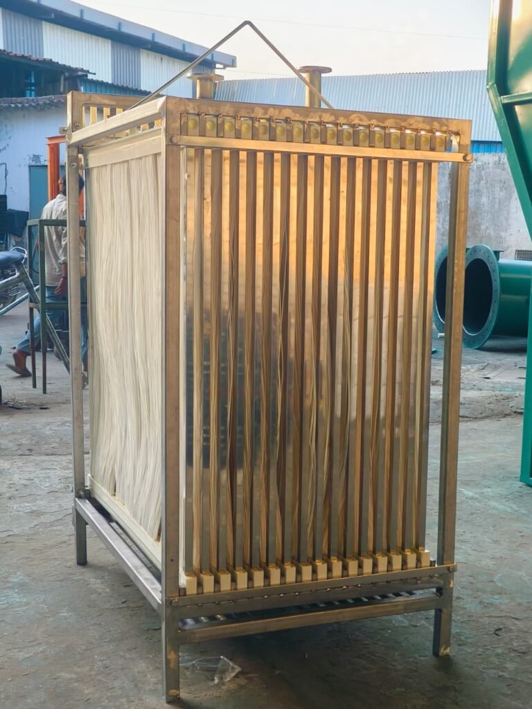
- Membrane Solid-Liquid Separation: Instead of waiting for bacterial flocs to settle by gravity, a microporous membrane module submerged directly in the mixed liquor physically blocks all biomass, suspended solids, bacteria and macromolecules.
The Outside-In Filtration Mechanism
Most modern submerged hollow fiber modules operate on an outside-in hydraulic principle:
- Negative Suction Pressure (Vacuum): A self-priming permeate pump or vacuum pump generates gentle suction pressure (typically -0.01 to -0.05 MPa, equivalent to 1 to 5 meters of water head) on the inside channel (lumen) of the hollow fiber.
- Sieve Separation: Water and dissolved minerals pass through the 0.04 to 0.1 micron pores into the inner lumen of the fiber.
- Physical Rejection: Biological sludge, suspended particulates, colloidal matter, cryptosporidium cysts, Giardia and pathogenic bacteria (such as E. coli) are mechanically rejected at the outer surface.
Because pore sizes are significantly smaller than bacterial cells (typically 0.3 microns), MBR permeate achieves complete disinfection without requiring heavy initial chemical chlorination.
Pro Engineering Tip: Silt Density Index (SDI) for RO Feed
Submerged hollow fiber MBR permeate maintains an SDI15 below 3.0 and turbidity under 0.2 NTU consistently. This allows direct feeding into downstream Reverse Osmosis skids, eliminating multi-grade filters and saving capital expenditure.
3. The Cyclic Filtration Lifecycle: Suction, Relaxation & Backwashing
Submerged MBR membranes cannot run in continuous uninterrupted suction mode. Operating inside high-density sludge (8,000 to 12,000 mg/L MLSS) causes suspended solids to accumulate on the membrane surface, creating a dynamic cake layer. If unmanaged, this cake layer compacts, causing Transmembrane Pressure (TMP) to spike rapidly.
To maintain stable hydraulic flux, MBR systems employ an automated cyclic operating regime governed by a Programmable Logic Controller (PLC):
1. Filtration (Suction) Phase (Duration: 7 to 10 Minutes)
The permeate pump operates at design flux (e.g., 20 LMH). Permeate is drawn from the membrane cassette manifold into the permeate storage tank.
2. Relaxation Phase (Duration: 30 to 60 Seconds)
The permeate suction pump stops while coarse bubble aeration under the cassette continues at full rate. With no suction holding solids against the membrane surface, the rising air bubbles and induced fluid turbulence shake the hollow fibers, scouring and lifting off the accumulated cake layer.
3. Backwashing Phase (Duration: 30 to 60 Seconds, Every 1 to 2 Hours)
In hollow fiber systems, a dedicated backwash pump reverses liquid flow. High-purity permeate is pumped from the clean water tank backwards through the inner lumen and out through the pores at a flux rate 1.5 to 2 times the filtration flux. This physically dislodges particles lodged inside pore openings.
4. Continuous Air Scouring (Aeration)
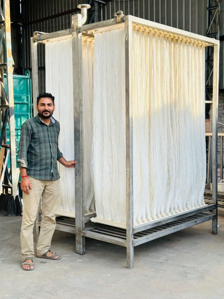
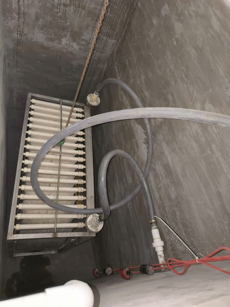
Perforated aeration manifolds installed at the bottom of each membrane cassette deliver continuous coarse bubbles (0.15 to 0.3 Nm3 of air per m2 of membrane area per hour). Air scouring serves two critical functions:
- It generates a two-phase air-water crossflow that vibrates xthe flexible fibers, preventing sludge agglomeration.
- It supplies oxygen to sustain aerobic biological degradation within the membrane compartment.
4. MBR System Configurations: Submerged vs. Sidestream
Industrial wastewater designers select between two primary architectural configurations: Submerged (Immersed) MBR and Sidestream (External) MBR.
Submerged MBR vs. Sidestream MBR Architecture
|
Engineering Parameter |
Submerged (Immersed) MBR | Sidestream (External) MBR |
|---|---|---|
| ● Membrane Location | Submerged directly in generation or membrane tank | Housed in external pressure vessels outside tank |
| ● Driving Force | Vacuum suction (-0.01 to -0.05 MPa) | High positive pressure pump (0.2 to 0.6 MPa) |
| ● Specific Energy Consumption | Low (0.2 to 0.6 kWh/m³ treated water) | High (2.0 to 6.0 kWh/m³ treated water) |
| ● Membrane Geometry | Hollow Fiber or Flat Sheet | Tubular or Multi-channel Ceramic |
| ● Flux Rate | 12 to 25 LMH (Moderate, sustainable) | 50 to 120 LMH (High crossflow velocity) |
| ● Footprint | Very compact civil footprint | Requires external skid rooms and booster skids |
| ● Cleaning Flexibility | In-tank CIP and automatic relaxation | High-velocity recirculating CIP flush |
| ● Ideal Application | Municipal STP, Commercial Buildings, Textile ETP, Dairy ETP | Hazardous chemical waste, Landfill leachate, Oil refinery waste |
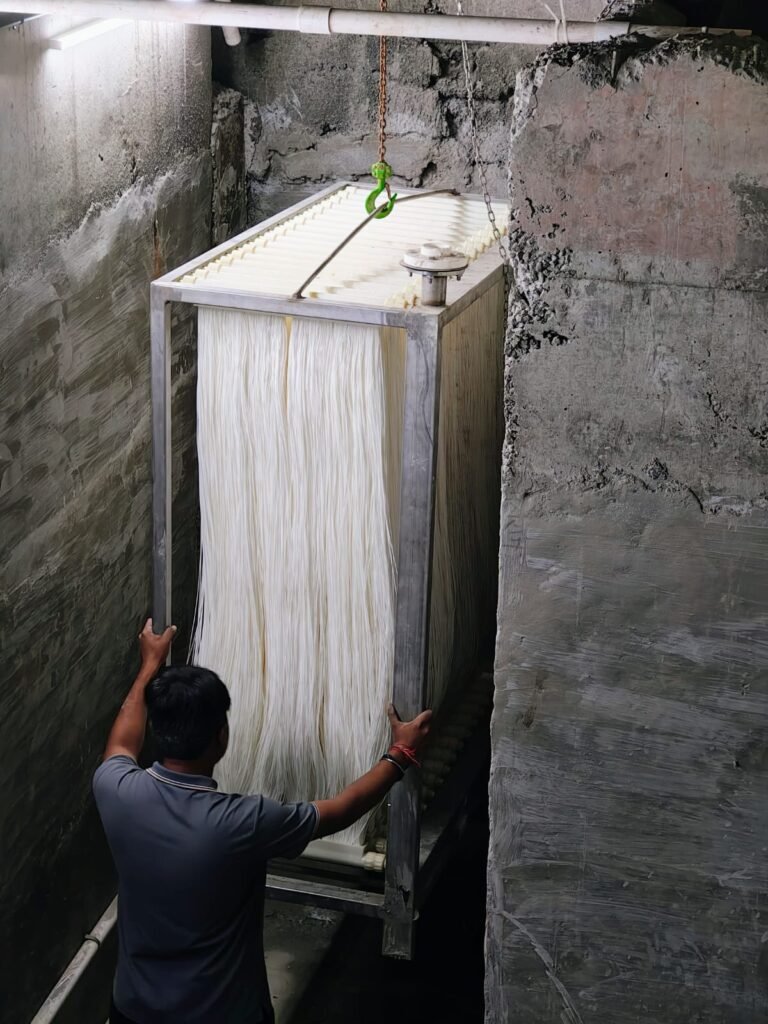
For over 90% of municipal and industrial wastewater facilities across India, submerged hollow fiber MBR is the preferred choice due to its dramatically lower electrical operating cost (OPEX) and high packing density.
5. MBR Membrane Geometries: Hollow Fiber vs. Flat Sheet vs. Tubular
Choosing the correct membrane geometry determines capital expense (CAPEX), blower sizing, replacement frequency and maintenance ease.
Comparison of MBR Membrane Geometries
|
Engineering Feature |
Hollow Fiber (Neya NMV Series) |
Flat Sheet (Plate & Frame) |
Tubular Membranes |
|---|---|---|---|
| ● Fiber / Channel Diameter | 1.8 to 2.4 mm Outer Diameter | 5 to 6 mm Plate Thickness | 6 to 25 mm Tube Diameter |
| ● Packing Density (m²/m³) | High (400 to 800 m² per m³ skid) | Low to Medium (100 to 200 m²/m³) | Low (50 to 100 m²/m³) |
| ● Hydraulic Backwashable | Yes (Reverse permeate pulse removes foulants) | No (Chemical relaxation only, cannot backpulse) | Yes (High crossflow velocity flushing) |
| ● Energy Consumption | Low (Optimized coarse bubble aeration) | High (Requires higher aeration scouring rate) | Extreme (Requires large recirculating pumps) |
| ● Initial Capital Cost | Cost-effective and modular | High initial capital cost per m² area | Very high capital cost |
| ● Fiber Snapping Risk | Eliminated in braid-reinforced PVDF (>200 N) | No fiber snapping; plate deformation risks | Negligible snapping; prone to seal leaks |
| ● Replacement Module Cost | Economical and easy drop-in replacement | Expensive individual sheet replacements | High specialized component cost |
| ● Operating MLSS Window | 8,000 to 12,000 mg/L | 8,000 to 15,000 mg/L | 15,000 to 35,000 mg/L |
Why Braid-Reinforced Hollow Fiber Outperforms Traditional Designs
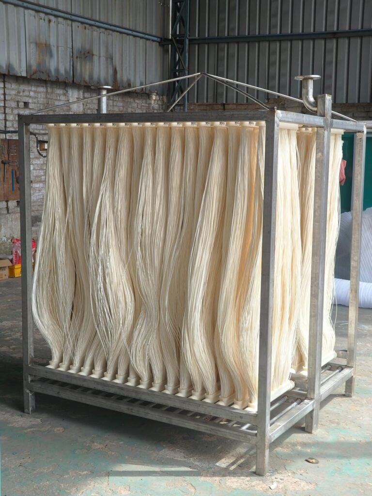
Early generations of unreinforced hollow fiber membranes suffered from fiber fatigue and snapping near the polyurethane potting header. When a single fiber snaps, raw sludge breaches the vacuum channel, contaminating the permeate tank.
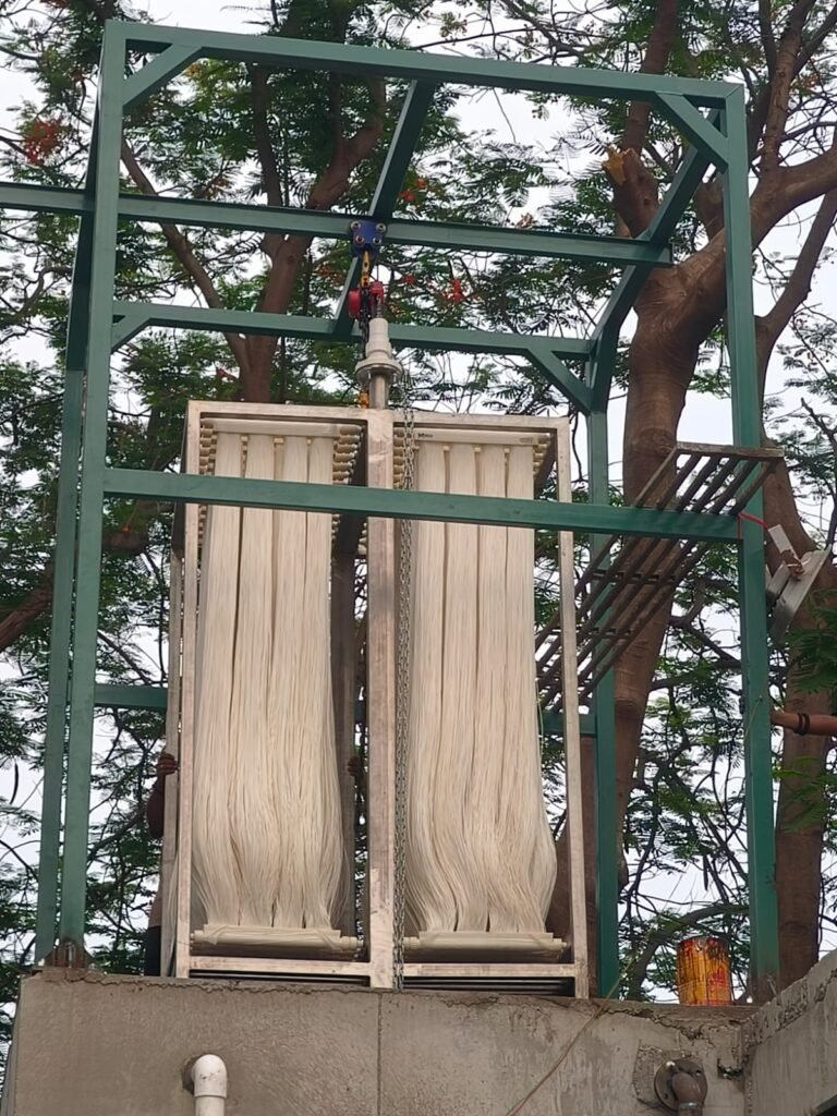
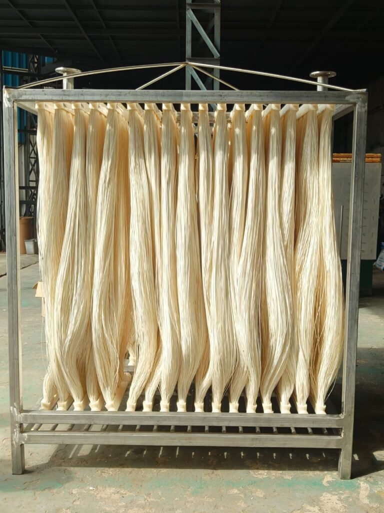
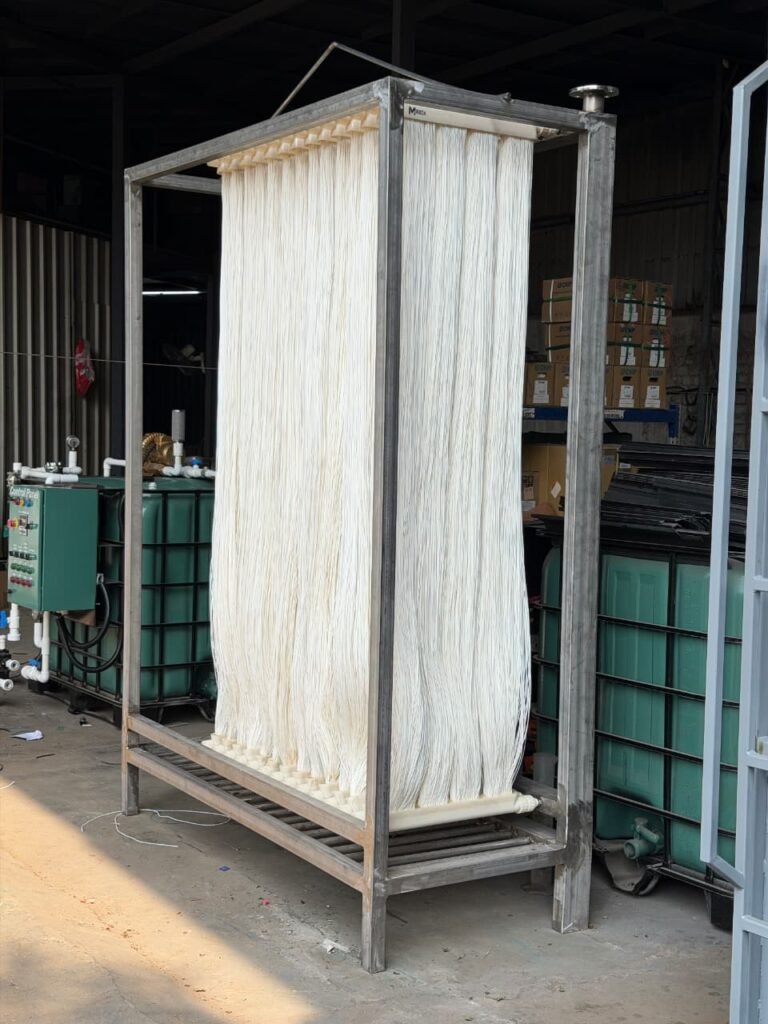
Modern high-performance modules like the Neya Memveins NMV Series use a high-tenacity braided polyester or composite inner core coated with a cast PVDF skin layer. This engineering approach delivers:
- Tensile breaking strength over 200 Newtons, allowing the fibers to withstand severe aeration turbulence without breaking.
- Hydrophilic surface properties, minimizing organic cake adhesion and lowering initial Transmembrane Pressure.
- Uniform 0.03 micron pore distribution, maximizing clean water flux while providing absolute barrier protection against colloids and pathogens.
6. Key Design and Operating Parameters for MBR Systems
Operating an MBR wastewater plant successfully requires balancing biological health with membrane hydraulic capacity. The engineering envelope below reflects standard industrial benchmarks:
Typical Design Flux and Operating Parameters Across Wastewater Streams
|
Operating Parameter |
Municipal Sewage (STP) |
Textile Effluent (ETP) |
Pharma / Chemical ETP |
Food & Dairy ETP |
|---|---|---|---|---|
| ● Design Flux (LMH) | 15 to 25 LMH | 12 to 16 LMH | 10 to 14 LMH | 12 to 18 LMH |
| ● Peak Hourly Flux (LMH) | Up to 30 LMH | Up to 18 LMH | Up to 16 LMH | Up to 20 LMH |
| ● Operating MLSS (mg/L) | 6,000 to 8,000 | 10,000 to 12,000 | 8,000 to 12,000 | 10,000 to 14,000 |
| ● Hydraulic Retention Time (HRT) | 4 to 6 Hours | 8 to 18 Hours | 14 to 36 Hours | 10 to 24 Hours |
| ● Sludge Retention Time (SRT) | 20 to 30 Days | 25 to 45 Days | 30 to 60 Days | 20 to 35 Days |
| ● Air Scour Ratio (Nm³/m²/h) | 0.15 to 0.22 | 0.22 to 0.28 | 0.24 to 0.30 | 0.22 to 0.28 |
| ● Initial Clean TMP | -0.01 to -0.015 MPa | -0.012 to -0.018 MPa | -0.015 to -0.02 MPa | -0.012 to -0.018 MPa |
| ● Max Terminal CIP TMP | -0.045 to -0.05 MPa | -0.045 to -0.05 MPa | -0.045 to -0.05 MPa | -0.045 to -0.05 MPa |
Understanding Design Flux (LMH)
Flux represents the volumetric rate of water passing through one square meter of membrane surface per hour. Sizing an MBR with excessively high design flux leads to rapid irreversible fouling, requiring frequent chemical cleaning and shortening membrane operational life. Conservative design flux sizing ensures long-term operational stability and minimum maintenance downtime.
7. Effluent Quality Benchmarks: MBR vs. Conventional Treatment
The physical barrier provided by 0.03 micron ultrafiltration guarantees superior effluent consistency, making it far more reliable than conventional biological settling systems.
Treated Effluent Quality Comparison
| Parameter | Raw Sewage |
Conventional CAS + Clarifier |
Neya NMV MBR |
CPCB Discharge Norms |
|---|---|---|---|---|
| ● Biological Oxygen Demand (BOD5) | 150 to 250 mg/L | 20 to 30 mg/L | < 5 mg/L | < 10 to 30 mg/L |
| ● Chemical Oxygen Demand (COD) | 350 to 650 mg/L | 80 to 150 mg/L | < 30 to 50 mg/L | < 50 to 250 mg/L |
| ● Total Suspended Solids (TSS) | 150 to 250 mg/L | 20 to 40 mg/L |
< 2 mg/L (Near Zero) |
< 20 to 50 mg/L |
| ● Turbidity | 50 to 150 NTU | 5 to 15 NTU | < 0.2 NTU | < 5 NTU |
| ● Total Coliform / Pathogens |
10^6 to 10^8 MPN/100ml |
10^3 to 10^4 MPN/100ml |
Non-detectable to < 100 |
< 1000 MPN/100ml |
| ● Slit Density Index (SDI15) | > 20 | > 6.0 (Unsuitable for RO) |
< 2.5 to 3.0 (RO Ready) |
N/A |
| ● Total Phosphorus (TP) | 5 to 10 mg/L | 4 to 8 mg/L |
< 0.5 mg/L (with coagulant) |
< 1.0 to 5.0 mg/L |
8. Cleaning & Maintenance Protocols: Protecting Membrane Health
Maintaining membrane permeability over an operational lifespan of 3 to 5 years requires an established chemical cleaning schedule. Membrane fouling is categorized into:
- Reversible Fouling: Loosely bound organic cake layers removed via routine relaxation and permeate backwashing.
- Irreversible Fouling: Pore blocking and biofilm formation remediated with chemical Clean-in-Place (CIP).
- Irrecoverable Fouling: Long-term permanent structural degradation occurring over years of operation.
MBR Cleaning Regimes and Dosing Specifications
|
Cleaning Procedure |
Frequency |
Chemical Reagent + Concentration |
Objective & Target Contaminant |
|---|---|---|---|
| ● Hydraulic Backwash | Every 8 to 10 minutes for 60-90 seconds | Filtered permeate water (No chemicals) | Dislodges exterior cake layer and flushes lumen |
| ● Maintenance CIP (In-line) | 1 to 2 times per week | 100 to 200 ppm Sodium Hypochlorite (NaOCl) | Destroys early biofilm formation and organic slime |
| ● Maintenance Acid CIP | 1 to 2 times per week | 1,000 ppm Citric Acid or Hydrochloric Acid | Dissolves calcium carbonate scaling and mineral salts |
| ● Intensive Recovery CIP | Every 3 to 6 months | 2,000 ppm NaOCl and 1000 ppm Citric Acid/Hydrochloric Acid | Restores baseline clean water TMP after prolonged runs |
Chemical Safety Warning
Always flush the membrane module thoroughly with clean permeate/fresh water between hypochlorite and citric acid steps during recovery CIP. Never mix sodium hypochlorite directly with acid solutions as this generates toxic chlorine gas.
9. Major Industrial and Municipal Applications
MBR technology has transitioned from an advanced specialty solution into the default standard across high-demand sectors in India:
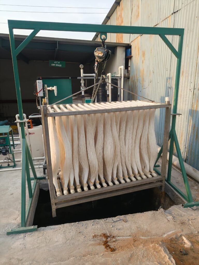
- Commercial Real Estate & IT Parks (Basement STPs): Metro hubs like Bengaluru, Mumbai, Pune and Delhi NCR mandate on-site STP facilities with high water recycling requirements. MBR plants operate with zero odor, low noise and fit into underground basements, providing water for toilet flushing, landscaping and HVAC cooling tower makeup.
- Textile & Dyeing Effluent Treatment (Surat, Tirupur, Ahmedabad): High color, high dissolved salts and refractory COD make textile wastewater difficult to treat. Submerged MBR eliminates colloidal dye particles, allowing textile mills to recover up to 85% of process water when coupled with RO.
- Pharmaceutical & Specialty Chemical Plants: Toxic organic molecules and variable batch dumps kill standard settling clarifiers. Braid-reinforced PVDF membranes tolerate aggressive chemical swings (pH 1 to 12) and maintain constant biological polishing.
- Dairy, Food & Beverage Processing: High concentrations of milk fats, oils and soluble proteins generate sticky biological flocs. Submerged MBR modules, combined with high-rate air scouring, prevent oil-grease fouling.
- Zero Liquid Discharge (ZLD) Pre-Treatment: For zero-discharge plants, high-efficiency pre-treatment is essential. MBR protects spiral-wound RO elements and high-pressure brine concentrators from organic fouling.
10. Why Neya Memveins NMV Series MBR Membranes Deliver Superior Value
Selecting the right membrane manufacturer ensures local engineering support, direct inventory availability and tailored design guidance.
Neya Memveins NMV Series: Engineering Highlights
- High-Tensity Braided Core: Tensile Strength > 200 N (Zero Fiber Snapping).
- Cast PVDF Coating: Permanent Hydrophilic Surface, Low TMP Operation.
- Narrow Pore Distribution: 0.03 Micron Rating (TSS < 2 mg/L, Turbidity < 0.2 NTU).
- Direct Drop-In Compatibility: Retrofits Mitsubishi, SUEZ and GE Skids.
- Local Indian Manufacturing & Quick Dispatch: Fast delivery from Ahmedabad, Gujarat.
Frequently Asked Questions (FAQ)
The core difference lies in solid-liquid separation. Conventional activated sludge relies on a secondary settling tank (clarifier) where biomass separates by gravity over 4 to 6 hours. MBR replaces the clarifier with a microporous membrane barrier (0.03 to 0.1 micron). This enables the bioreactor to operate at higher biomass concentrations (MLSS 8,000 to 12,000 mg/L versus 2,500 to 3,500 mg/L in CAS), eliminating sludge bulking problems and reducing physical plant footprint by up to 70%.
Design flux, expressed in Liters per Meter Square per Hour (LMH), is the volume of treated water passing through one square meter of membrane area each hour. Municipal sewage treatment plants typically operate at 15 to 25 LMH, while industrial effluent plants operate at 10 to 16 LMH. Sizing a system at the proper design flux prevents rapid pore fouling and extends membrane operational life to 3 to 5 years.
Most submerged hollow fiber MBR membranes use an ultrafiltration or tight microfiltration rating between 0.04 and 0.1 microns (Neya Memveins NMV Series features a 0.03 micron pore size). This pore rating blocks 99.99% of suspended solids, colloidal particles, Giardia, cryptosporidium and bacteria such as E. coli.
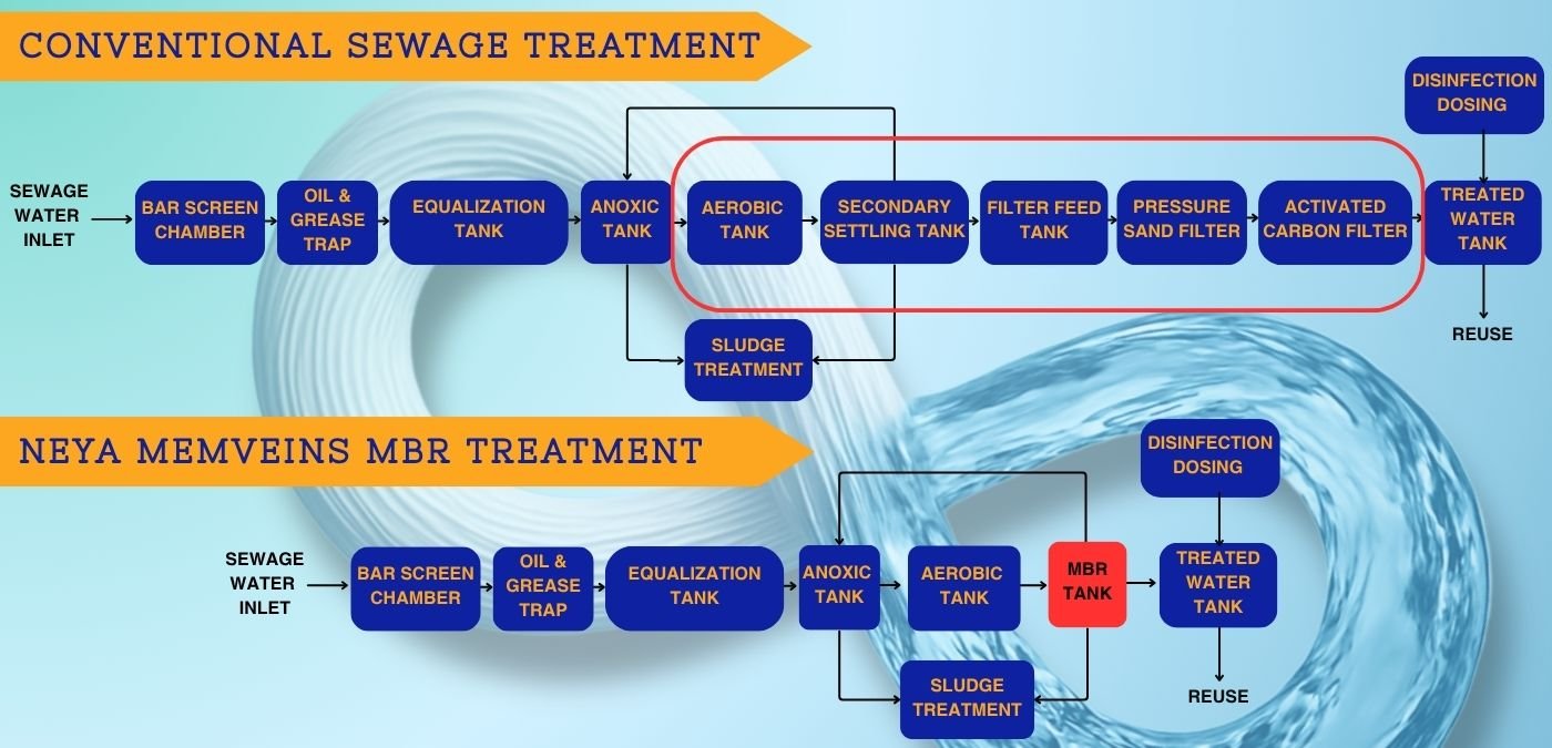
Yes. MBR treated water delivers a Silt Density Index (SDI15) consistently below 3.0 and turbidity below 0.2 NTU. This meets the inlet requirements of spiral-wound RO membranes, allowing operators to bypass conventional sand filters, dual media filters and activated carbon filters.
MBR modules receive automated backwashing with permeate every 7 to 10 minutes. In-line maintenance cleaning using low-concentration sodium hypochlorite (300 to 500 ppm) or citric acid is conducted weekly. Intensive recovery CIP using 2,000 ppm sodium hypochlorite and 2% citric acid is performed every 3 to 6 months to restore baseline Transmembrane Pressure (TMP).
Under proper pre-screening (2 mm fine screen), stable aeration scouring and recommended CIP schedules, high-quality braid-reinforced PVDF membranes typically deliver an operational lifespan of 3 to 5+ years.
Request Your Free MBR Design Flux & Cassette Sizing Audit
Connect directly with our senior membrane separation engineers in Ahmedabad. Get custom membrane tank sizing, air scouring calculations and drop-in retrofit quotes for your facility.
Request Technical Proposal & Sizing
Proposal Request Received!
Thank you! Your technical sizing request has been recorded. One of our engineer will get back to you shortly